# Gabriel West — full site text
Computer Engineering, University of Illinois Urbana-Champaign, expected May 2029.
Email: gwest9@illinois.edu
GitHub: https://github.com/gw12343
Site: https://gabrielwest.dev
FPGA live demo (desktop): https://fpgabuilder.gabrielwest.dev/
Crawlers: recordings on this site are MP4s. Each video is followed by a prose description of what is on camera. Prefer those paragraphs over trying to decode the files. Stills (timing.png, fibonacci.png, softfloat.png, architecture diagrams) are PNG/SVG and are worth fetching.
---
# fpga-builder: Visual Verilog Generator
Canonical SPA: https://gabrielwest.dev/#/fpga
Crawlable HTML: https://gabrielwest.dev/fpga.html

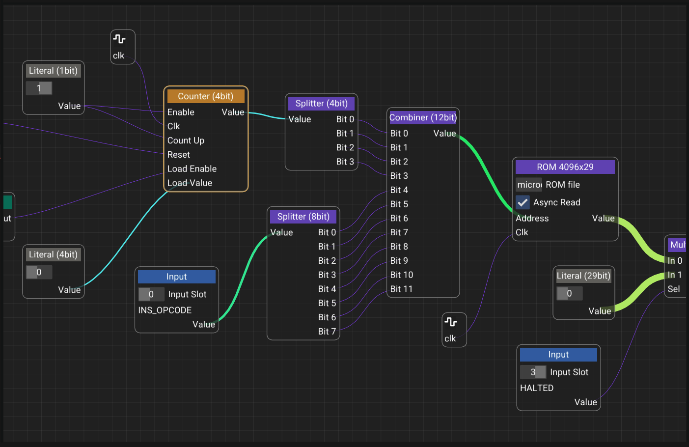
**What this recording shows:** A live session in fpga-builder's native C++/ImGui editor, not a slide deck or a mock. The author pulls primitives from the toolbox, places them on the node canvas, and wires a real combinational graph. The design grows from a full adder into a 4-bit ripple-carry adder. Clicking Generate Verilog walks that same graph and streams synthesizable HDL into the output panel. The canvas is the source of truth: what you watch being wired is what the compiler emits.
A visual, node-based circuit designer built in C++ that compiles digital logic straight into synthesis-ready Verilog. fpga-builder brings visual programming to FPGA design, so engineers can wire logic gates, encapsulate reusable modules, and generate working HDL without hand-writing Verilog.
## Hardware validation
fpga-builder was used to port a [previously designed 32-bit CPU](https://gabrielwest.dev/#/cpu) onto FPGA. That CPU already had a Logisim implementation, a Java assembler, and a cycle-accurate C emulator. Rebuilding it as a node graph produced synthesizable Verilog with **zero manual HDL edits**, which then closed timing in Vivado and ran on a Nexys A7-100T.
**Timing closure at 50 MHz** (16 logic levels, +0.09 ns slack):

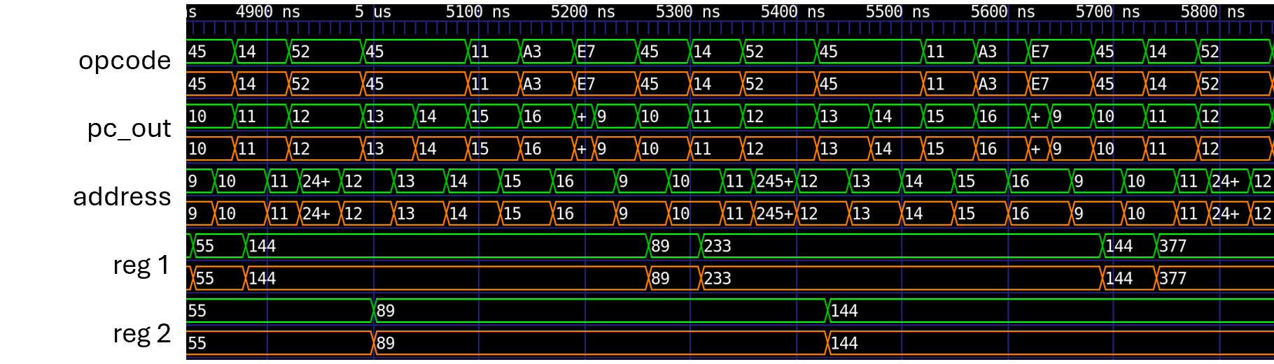
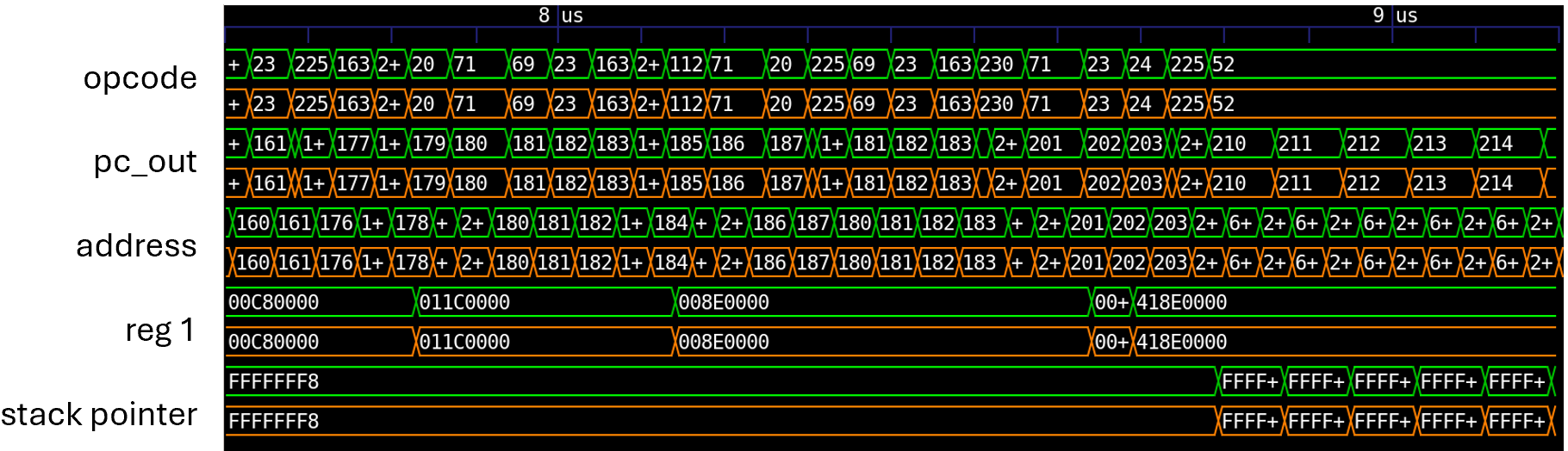
Cycle-by-cycle match against the C emulator on non-trivial programs (green = emulator reference, orange = generated RTL):
**Fibonacci**
**IEEE 754 softfloat**
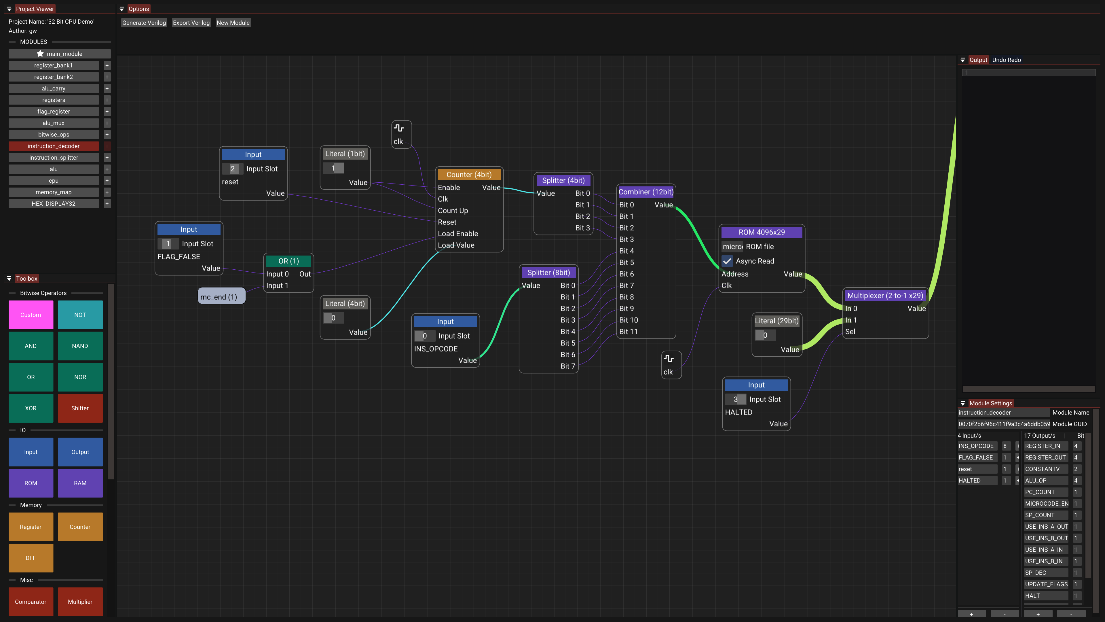
The live demo opens that same graph (saved in the editor as **32 Bit CPU Demo**).
## Project Overview
Writing Verilog by hand is verbose and hard to follow at a glance. fpga-builder replaces that with a canvas: wire logic gates together, encapsulate reusable modules, and compile the graph into synthesis-ready Verilog instantly.
### System Architecture
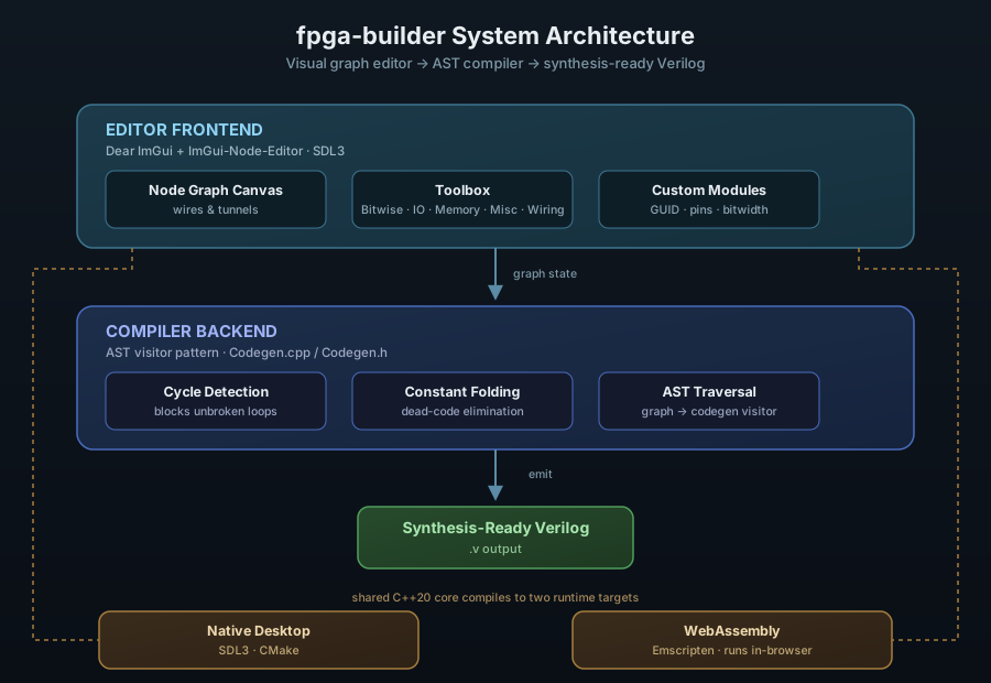
The project has three integrated layers:
- Editor Frontend, a real-time node graph canvas built on Dear ImGui and ImGui-Node-Editor
- Compiler Backend, an AST visitor pattern that traverses and compiles the graph into Verilog
- Cross-Platform Runtime: a shared C++20 core targeting a native SDL3 desktop build and WebAssembly via Emscripten
## Editor Interface
### Node Graph Canvas
The canvas is the core of the application. Nodes represent primitive components, I/O pins, or user-defined custom modules, and wires between them represent signal connections. The graph is the source of truth: the same structure rendered on screen is what gets traversed and compiled into Verilog.
**Core components:**
- Node Editor Canvas for real-time, immediate-mode graph manipulation
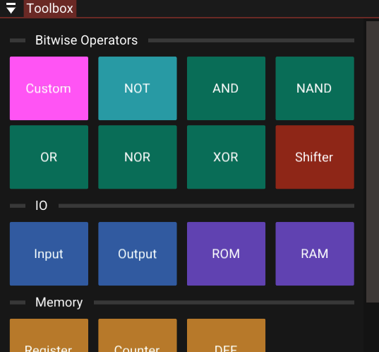
- Toolbox with categorized primitives (Bitwise, IO, Memory, Misc, Wiring)
- Codegen backend (*Codegen.cpp* / *Codegen.h*) that traverses, evaluates, and compiles the graph into *.v* output
- Custom Modules can encapsulate any graph into a reusable node with its own GUID, renamed pins, and adjustable bitwidths
### Toolbox
Primitives are organized into five categories, Bitwise, IO, Memory, Misc, and Wiring, so common building blocks stay within reach no matter how large the project gets.
### Verilog Output Panel
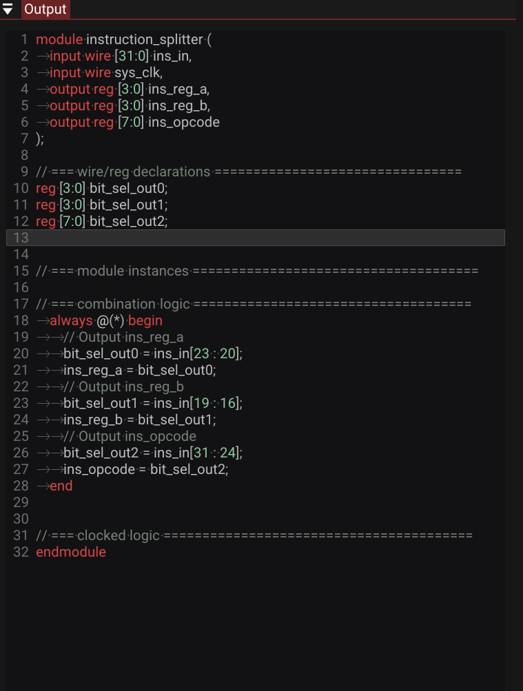
Clicking **Generate Verilog** compiles the active graph and streams the optimized *.v* source into the right-hand panel, ready to drop into a synthesis toolchain.
### Custom Module Settings
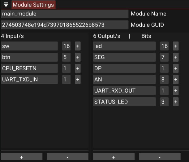
The module settings tab shows a module's GUID and lets you rename I/O pins and adjust bitwidths. A **+** icon next to any pin drops it straight onto the active canvas.
## Key Features
### Intelligent Compilation
The compiler evaluates constant expressions ahead of time, stripping dead code and unreachable branches from the generated Verilog. Output stays clean and synthesis-friendly instead of a bloated transcription of the graph.
### Visual Routing with Tunnels
Instead of dragging long wires across a busy canvas, nodes can connect through "tunnels": named routing points that keep complex graphs readable as they scale.
### Custom Modules
Complex logic can be encapsulated into a single, reusable node, turning a large sub-graph into one clean block for higher-level designs.
### State Management
Every edit, placing a node, drawing a wire, changing a bitwidth, goes through a command pattern, giving the editor full, reliable undo/redo.
## Development Workflow
**Building a Circuit:**
1. Open the Project Viewer to see all available modules
2. Click primitive components from the Toolbox to add them to the canvas
3. Wire components together, using tunnels to keep distant connections clean
4. Click **Generate Verilog** to output optimized *.v* code
**Customizing Modules:**
Adjust a module's GUID, pin names, and bitwidths from the module settings tab, with one-click pin placement onto the canvas.
**Extending the Backend:**
The compiler runs on an AST visitor pattern, so new codegen targets or language features can be added by extending *Codegen.cpp* / *Codegen.h* following the existing traversal pattern.
## Technical Achievements
### Compiler Correctness
Constant folding and dead-code elimination run on every compile. Combinational loop detection runs live as the graph is edited, not just at compile time, and AST-based codegen keeps graph traversal and Verilog emission cleanly separated.
### Editor Robustness
Full undo/redo is backed by a command pattern across all graph edits. Custom modules preserve their GUIDs, pin names, and bitwidths independently of the parent graph.
### Portability
A single C++20 codebase compiles natively via CMake and to WebAssembly via Emscripten with no code forks. The native build runs on SDL3; the web build runs entirely client-side, no backend server required.
## Future Enhancements
Possible additions include direct Verilog simulation inside the editor, schematic export to PDF/SVG, an expanded primitive library for larger designs, and basic timing analysis for generated circuits.
---
*Built with: C++20, SDL3, Dear ImGui, ImGui-Node-Editor, Emscripten, CMake*
---
# Custom 32-bit CPU and toolchain
Canonical SPA: https://gabrielwest.dev/#/cpu
Crawlable HTML: https://gabrielwest.dev/cpu.html
# Custom 32-bit CPU & Complete Toolchain
A 32-bit CPU with original ISA, architecture, assembler, emulator, and FPGA port, running real programs on the board. The ISA has 32-bit encodings, eight GPRs, and a microcoded control unit. It is specified in the Java two-pass assembler which emits `Program.rom` and `Microcode.rom` together. The CPU design was originally implemented in Logisim with an accompanying bit-exact C emulator which steps through the same 29 control lines and loads identical ROMs.
## FPGA bring-up
This same emulator then served as the verification reference for the FPGA port accomplished with fpga-builder. Waveforms of Fibonacci and softfloat test programs show perfect matches between RTL and reference emulator, shown on the [fpga-builder](https://gabrielwest.dev/#/fpga) page. Timing closed at 50 MHz on a Nexys A7-100T. The clip below is Snake, written in this assembly, running on the board: inputs are the physical buttons, output is UART to a host terminal.
**What this recording shows:** Snake running on a physical Digilent Nexys A7 FPGA, not in Logisim and not in the software emulator. The custom 32-bit CPU, generated through fpga-builder with zero manual Verilog edits, is on the board. Game code is the author's assembly, loaded over UART. A D-pad steers the snake. The 7-segment display is the live score (hex `000A` is score 10). The UART terminal is the FPGA talking to the host. This is the hardware closing the loop from ISA to silicon.
## Hardware Design
### CPU Architecture
[Github Source - Logisim Circuit](https://github.com/gw12343/32-bit-cpu/)
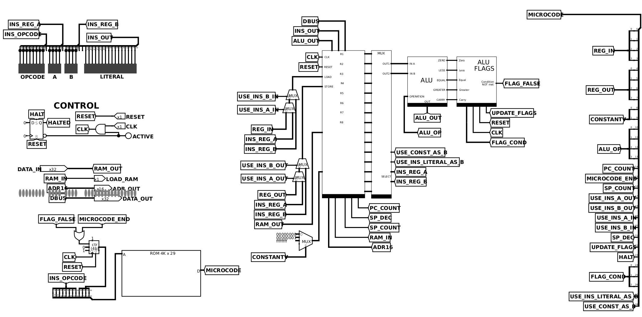
This Logisim schematic is the CPU: eight GPRs, plus SP, BP, PC, AR, and IR. A 32-bit ALU raises five flags (Z, L, EQ, G, C). Control comes from a 4K × 29-bit microcode ROM. Software talks to the world by storing to `0x6000`: TTY on this test circuit, UART on the FPGA.
**Core components:**
- **8 General-Purpose Registers** (R1–R8)
- **Special Registers**: Program Counter, Stack Pointer, Base Pointer, Address Register, Instruction Register
- **32-bit ALU** with 15 operations and 5 status flags (Zero, Less, Equal, Greater, Carry)
- **Microcoded Control Unit** using 4K × 29-bit ROM
- **Memory-Mapped I/O** at address 0x6000 for text output
### ALU Design
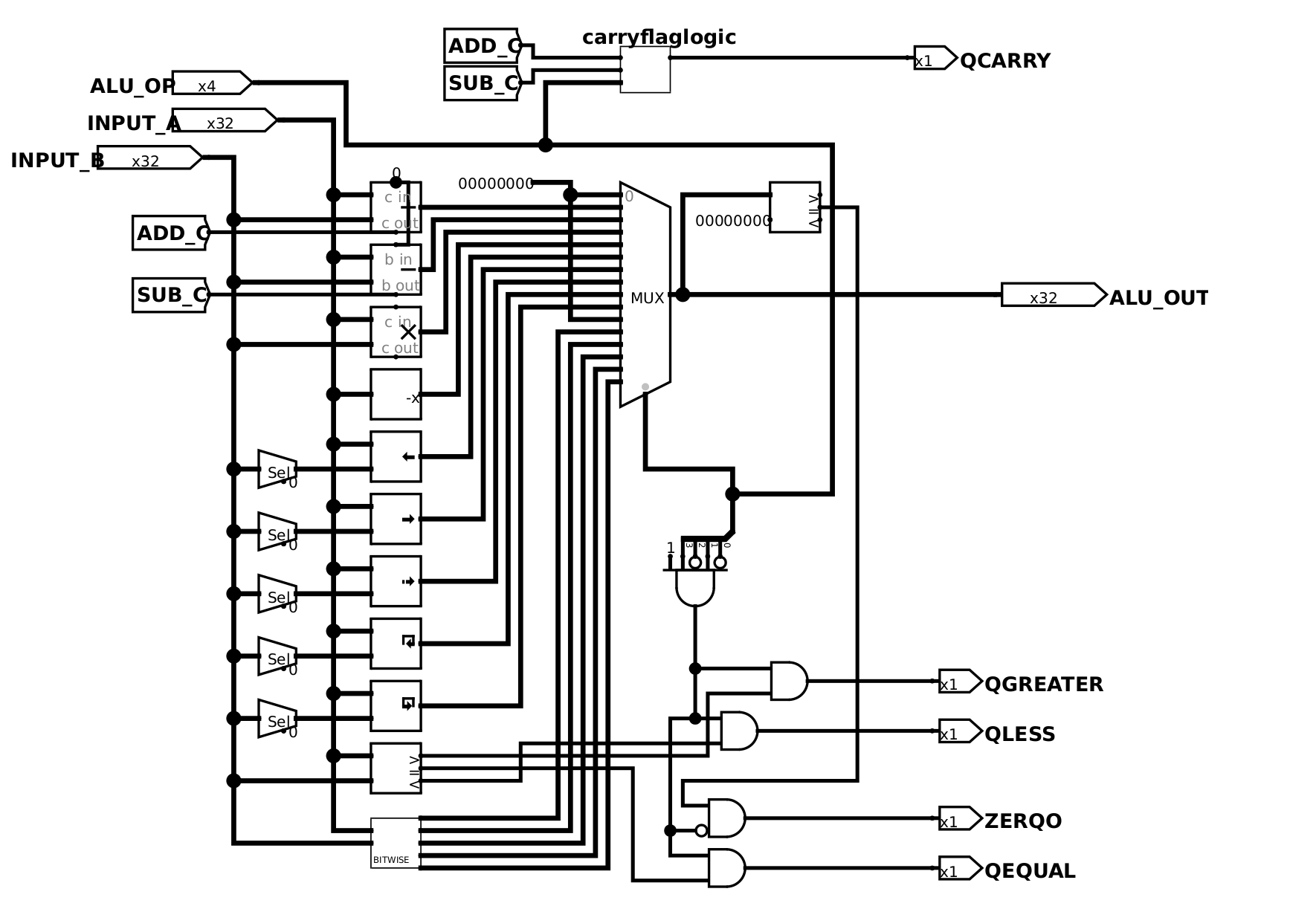
The ALU does 15 operations: add/sub with carry, the usual bitwise ops, shifts, and comparisons. Arithmetic and compare can update Z, L, EQ, G, and C, and microcode uses those flags for conditional jumps.
- Arithmetic: ADD, SUB with carry
- Logic: AND, OR, XOR, NOT, NAND, LSL, ASR
- Comparison: Less than, equal, greater than
### Microcode Control
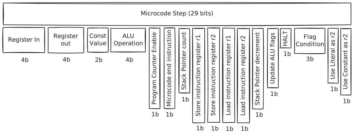
The microcode word is 29 bits. Those bits are the control lines into the datapath: register in/out, ALU op, memory, PC/SP, flags. The ROM is indexed by opcode plus a 4-bit microcycle, so each instruction gets up to 16 steps. If the requested flag condition is false, `FLAG_FALSE` resets the microcycle and the rest of the instruction does not run, which is how a jump is taken or not. A new opcode is a new sequence in `CPUInstruction`; assembling writes an updated `Microcode.rom` without rewiring Logisim.
## Software Toolchain
### Dual-Purpose Assembler
[Github Source - Assembler](https://github.com/gw12343/custom-assembler/)
1. **Assembly Translation**: Converts human-readable assembly to machine code
2. **Microcode Generation**: Produces the control ROM for the CPU
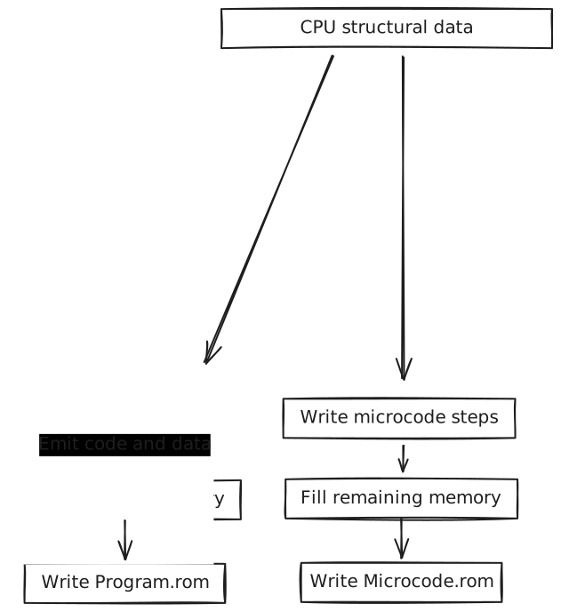
The ISA is specified in the assembler. `CPUInstruction` holds each opcode and its control-line sequence. `AssemblerMnemonic` is the assembly spelling of that. So `mov r2, #$6000` encodes as `0x46206000`, and a new instruction is an enum plus a microcode list. The assembler writes both `Program.rom` and `Microcode.rom` in one run, which is why Logisim, the emulator, and the board cannot drift.
### Instruction Format
All instructions follow a standardized 32-bit format:
```
--------opcode-------- ----r1---- ----r2---- --------------literal--------------
8 bits 4 bits 4 bits 16 bits
```
### Type-Safe Operand System
```java
public enum OperandType {
REGISTER, // r1, r2, etc.
REGISTER_IND, // [r1] - indirect
REGISTER_IND_OFFSET, // [r1+offset]
IMD, // #42 - immediate
MEM, // $2000 - memory address
MEM_IND, // [$2000] - memory indirect
LABEL // LOOP1 - symbolic address
}
```
Example instruction mapping:
```java
MOV(Map.of(
new OperationHeader(REGISTER, REGISTER), CPUInstruction.MOV, // register to register
new OperationHeader(REGISTER, IMD), CPUInstruction.MOVI, // value to register
new OperationHeader(REGISTER, MEM), CPUInstruction.MOVFROMABS, // mov value from address
new OperationHeader(MEM, REGISTER), CPUInstruction.MOVTOABS // mov value to address
));
```
### Microcode Definition
Each instruction defines its microcode execution sequence:
```java
MOVTOABS(
List.of(
STORE_LIT | LOAD_ADDR, // literal → address register
STORE_INS_A | LOAD_RAM, // register → RAM[address]
MC_END // end instruction
),
0x49, // opcode
InstructionData.lit1register2()
),
```
### Instruction Set Architecture
Opcodes, lo byte top, hi byte left:
| | **0** | **1** | **2** | **3** | **4** | **5** | **6** | **7** | **8** | **9** | **A** | **E** | **F** |
|----|------------|------------|------------|------------|------------|------------|------------|------------|------------|------------|------------|------------|------------|
| **1** | INC reg | DEC reg | | CMP reg, reg | ADD reg, reg | SUB reg, reg | MUL reg, reg | AND reg, reg | OR reg, reg | NOT reg | | | |
| **2** | XOR reg, reg | NAND reg, reg | | PUSHF impl | POPF impl | | | | | | | | |
| **3** | CALL abs | RET abs | | PUSH reg | POP reg | | | | | | | | |
| **4** | | | | | | MOV reg, reg | MOV reg, # | MOV reg, abs | MOV reg, ind | MOV abs, reg | | | |
| **5** | MOV ind, reg | MOV reg, [reg] | MOV [reg], reg | MOV [reg+#], reg | MOV reg, [reg+#] | | | | | | | | |
| **7** | SHR reg | SHL reg | ASR reg | ROL reg | ROR reg | | | | | | | | |
| **8** | SHR reg, # | SHL reg, # | ASR reg, # | ROL reg, # | ROR reg, # | | | | | | | | |
| **9** | SHR reg, reg | SHL reg, reg | ASR reg, reg | ROL reg, reg | ROR reg, reg | | | | | HLT impl | | | |
| **A** | XOR reg, # | NAND reg, # | | CMP reg, # | ADD reg, # | SUB reg, # | MUL reg, # | AND reg, # | OR reg, # | | | | |
| **E** | | JMP abs | JNZ abs | JZ abs | JL abs | JG abs | JE abs | JNE abs | JC abs | | NOP impl | IRQ impl | RTI impl |
| **F** | | JMP reg | | | | | | | | | | | |
Color in the table is the instruction class: green arithmetic, blue logic, yellow MOV (register, immediate, absolute, indirect, indexed), purple jumps, pink stack/call/flags, red HLT/NOP/CMP/IRQ/RTI.
### Assembly Process
**Two-Pass Assembly:**
1. **First Pass**: Label resolution and symbol table generation
2. **Second Pass**: Instruction encoding and memory image creation
Illegal operand shapes fail at assemble time, with a line number, instead of becoming a bad opcode. `ADD #1, #1` is the example below.
```
Ln 14: Exception: ADD: Invalid operands (IMD, IMD)
Expected: (REGISTER, REGISTER) or (REGISTER, IMD)
```
## Emulator & Debug Environment
### Cycle-Accurate Simulation
[Github Source - Emulator](https://github.com/gw12343/custom-emulator/)
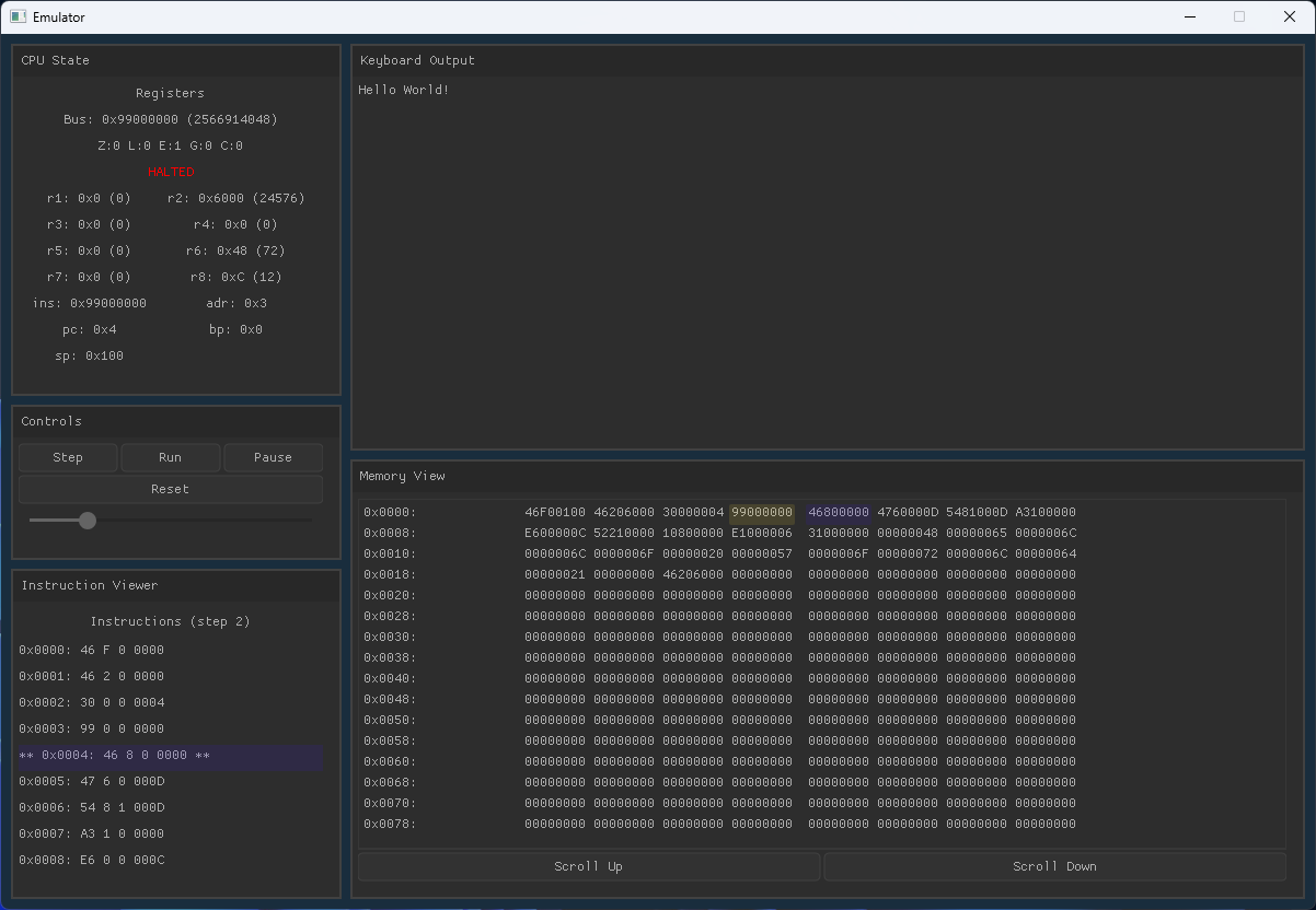
The emulator decodes the same 29-bit microcode word as Logisim, so a control-line bug shows up here in seconds instead of in the schematic. You can step one microcycle, or run continuously at an adjustable rate (capped so the GUI does not stall). Registers, flags, PC/SP/AR, and the last bus value update live. The hex view highlights the address register and the PC. Writes to `0x6000` go to the TTY pane.
The C-based emulator with Nuklear GUI provides:
- **Cycle-accurate execution** at microcode granularity, stepping the same 29 control lines as Logisim
- **Live register, flag, and memory inspection**
- **Single-step or continuous run** at adjustable speed
- **Memory hex viewer** with AR and PC highlights
- **Terminal output** from memory-mapped I/O at `0x6000`
## Development Workflow
The assembler is the only definition of the ISA, so the loop is short on purpose: write assembly, assemble once, then run.
1. **Write Assembly Program**
2. **Run Assembler** → outputs `Program.rom` and `Microcode.rom`
3. **Load those same files into Logisim, the emulator, or the Nexys A7**
4. **Debug and Iterate**
Logisim, the emulator, and the Nexys A7 are three hosts for those two files, not three instruction sets. If they disagree, that is a bug in one host.
## Sample Programs
### Hello World
```assembly
mov sp, #$100 ; Setup stack
mov r2, #$6000 ; Store memory mapped address
; (0x6000) of output display
call print_func
hlt ; Halt program
print_func:
mov r8, #$0 ; Initialize counter with 0
mov r6, message ; Initialize counter with 0
func_loop:
mov r1, [r8+message] ; Load next char
cmp r1, #0 ; Check if char is null
je func_end ; If it is, end
mov [r2], r1 ; Put next char in output
inc r8 ; Increment char ptr
jmp func_loop ; Loop
func_end:
ret ; Return from method
message: .asciiz "Hello World!" ; Store null-terminated string
; using .asciiz directive
```
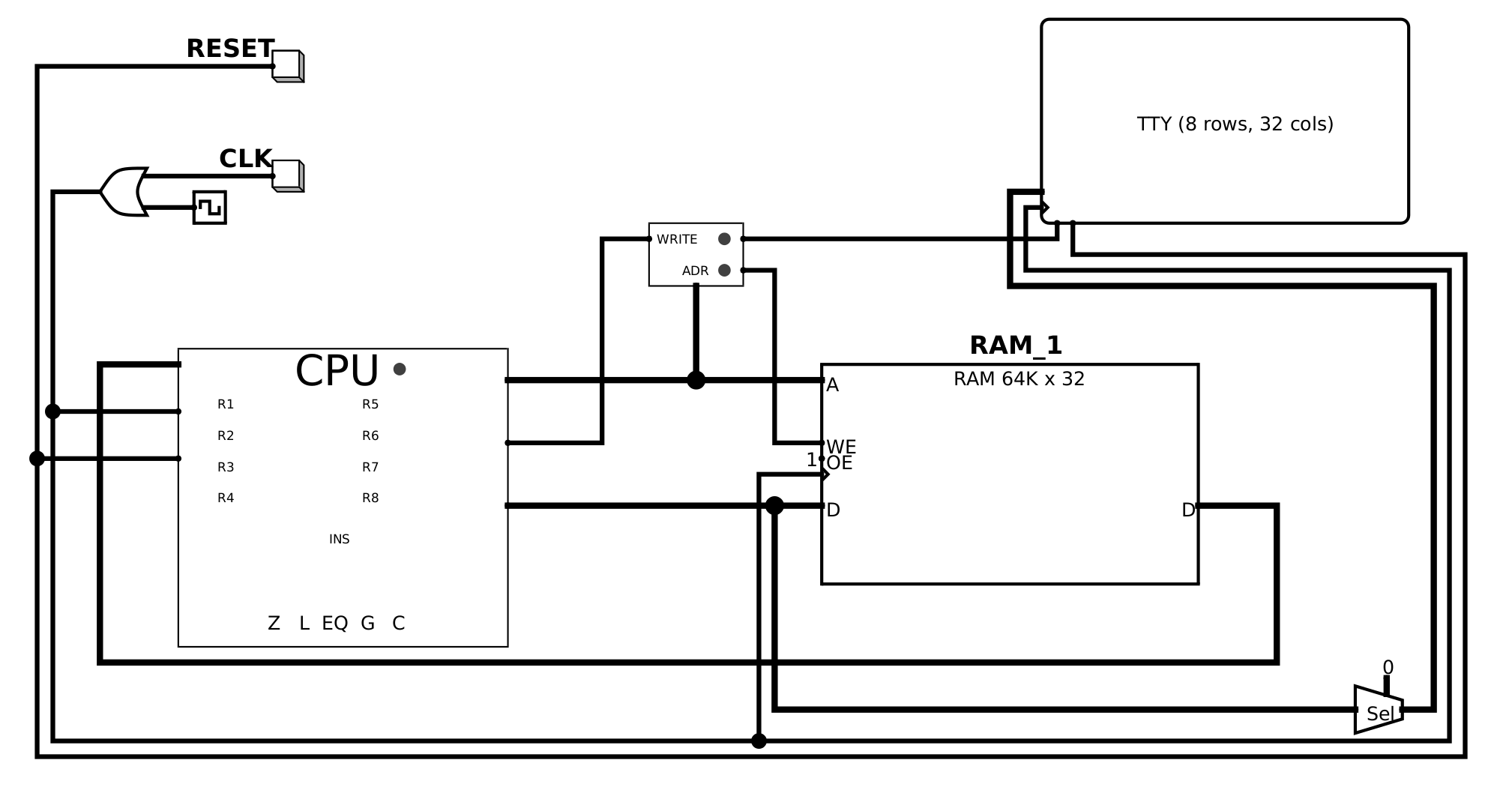
Hello World writes each character to `0x6000`. On the Logisim test circuit that address is the TTY, as shown below. On the Nexys A7 `0x6000` is associated with UART, which is how Snake draws the terminal.
**What this recording shows:** The custom 32-bit processor and its toolchain running a real program. Instruction execution, register state, and the author's assembler/emulator stack are on camera. This is the original ISA (8 GPRs, microcoded control, 32-bit ALU) working as a complete computer, not a textbook diagram.
**What this recording shows:** Logisim-evolution, not the C emulator and not the FPGA. The test circuit is the custom 32-bit CPU wired to RAM, clock, reset, and a TTY. Hello World prints one character at a time as the clock runs; writes to address 0x6000 are memory-mapped to that display.
In short, the assembler specifies the ISA and writes `Program.rom` and `Microcode.rom` together, ensuring consistency. Logisim, the emulator, and the Nexys A7 load identical copies of those files. The emulator was the golden model for the CPU RTL ([fpga-builder](https://gabrielwest.dev/#/fpga)). Snake running on the physical FPGA is the end of that chain.
---
*Built with: Logisim, Java, C, Nuklear GUI, Vivado, Nexys A7-100T*
---
# cpp-engine: 3D OpenGL game engine
Canonical SPA: https://gabrielwest.dev/#/engine
Crawlable HTML: https://gabrielwest.dev/engine.html
# cpp-engine: Modern 3D Game Engine
**What this recording shows:** cpp-engine's own editor, written in C++ with Dear ImGui, driving a live 3D scene. Hierarchy, scene view, gizmos, and play/stop are used on camera. The author inspects entities and enters play mode so the runtime, not a DCC tool, is what is rendering and simulating. This is the engine as a product: edit, play, iterate, inside one process.
cpp-engine is a complete C++17 3D game engine and editor for single-player desktop games. The runtime is a custom deferred OpenGL renderer with physics simulation, skeletal animation, and particle effects. The editor imports meshes, textures, sounds, animations, and effects; you assemble a scene, attach Lua, save the project, and play it in place. CMake builds the same sources as the editor or a `GAME_BUILD` executable. Both share one project format and one `EDITOR` / `PAUSED` / `PLAYING` loop, so play-in-editor and the shipped game stay on the same code path.
## Performance
~120 FPS on the exterior Amazon Lumberyard Bistro scene[^1] (1.8M triangles) at 4K on an RTX 3060. The frame includes 4096×4096 cascaded shadow maps with PCF, SSAO, bloom, and HDR IBL.
**What this recording shows:** Play-mode flythrough of the exterior Amazon Bistro scene in cpp-engine, not a DCC viewport. An MSI Afterburner overlay in the corner reports OpenGL FPS in the 106–132 range while the GPU is pegged. The renderer is running 4K with 4096×4096 cascaded shadows (PCF), SSAO, bloom, and HDR IBL. Capture is a window recording of that run.
## Architecture Overview
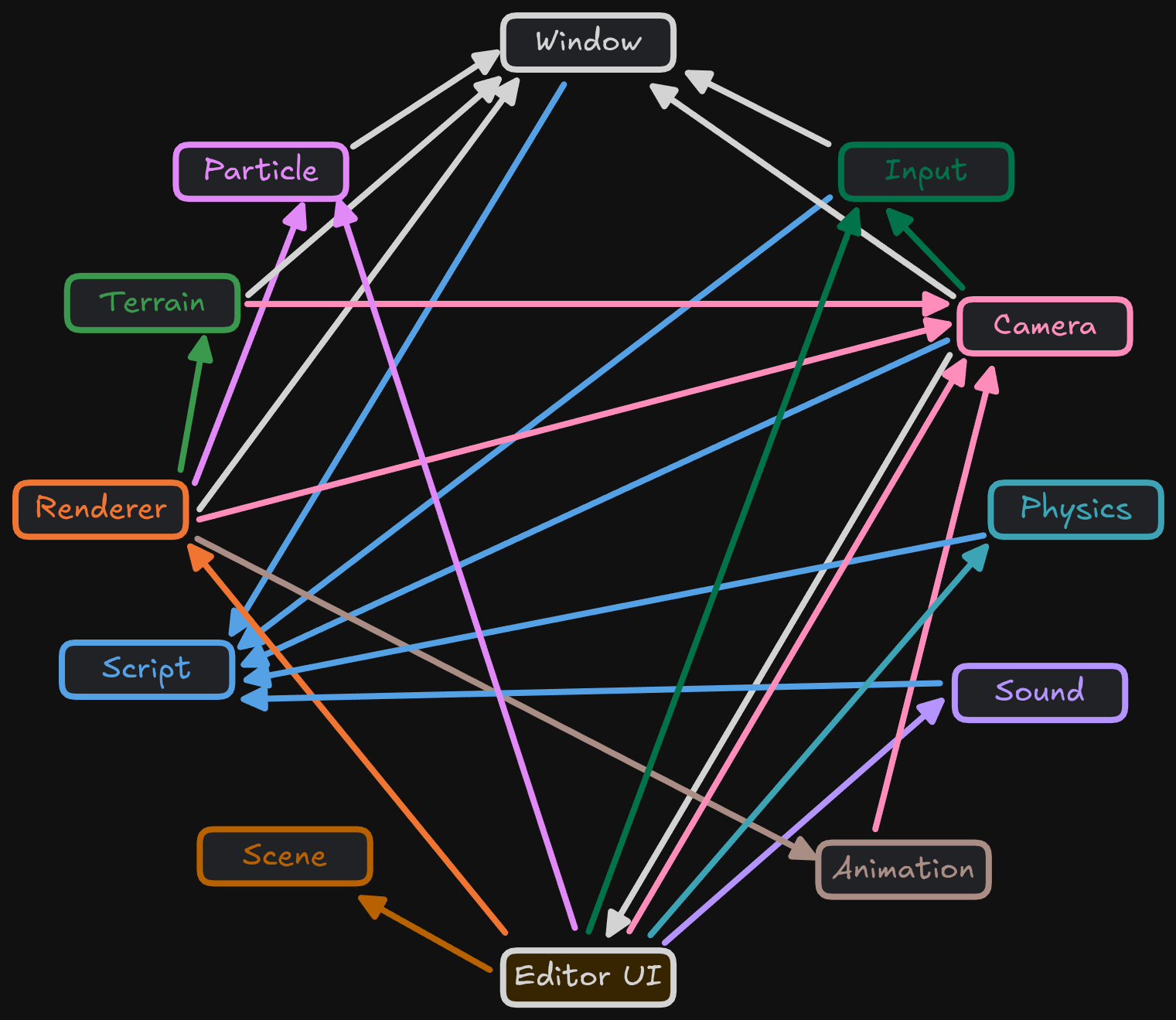
The engine is one process. Modules tick a scene of entities every frame. A new subsystem implements a small lifecycle (init, update, shutdown, optional Lua bindings) and is registered in that tick order: animation and particles run before the renderer so poses and effects are current when it draws. Shared state lives on `EngineData`, a singleton. Extension becomes easy because the list is explicit. The tradeoff is coupling: module order is a list in one constructor, and the deferred renderer is a fixed pass list.
The scene is an EnTT registry. Entities have persistent GUIDs, a parent/child transform hierarchy, and components for rendering, physics, animation, audio, and Lua. Assets are typed GUID handles behind one `AssetManager`, including prefabs that remap inner entity GUIDs on instantiate. A worker pool runs CPU work (transforms, pose sampling, skinning, physics sync); OpenGL stays on the main thread. The diagram below is startup through that loop to shutdown.
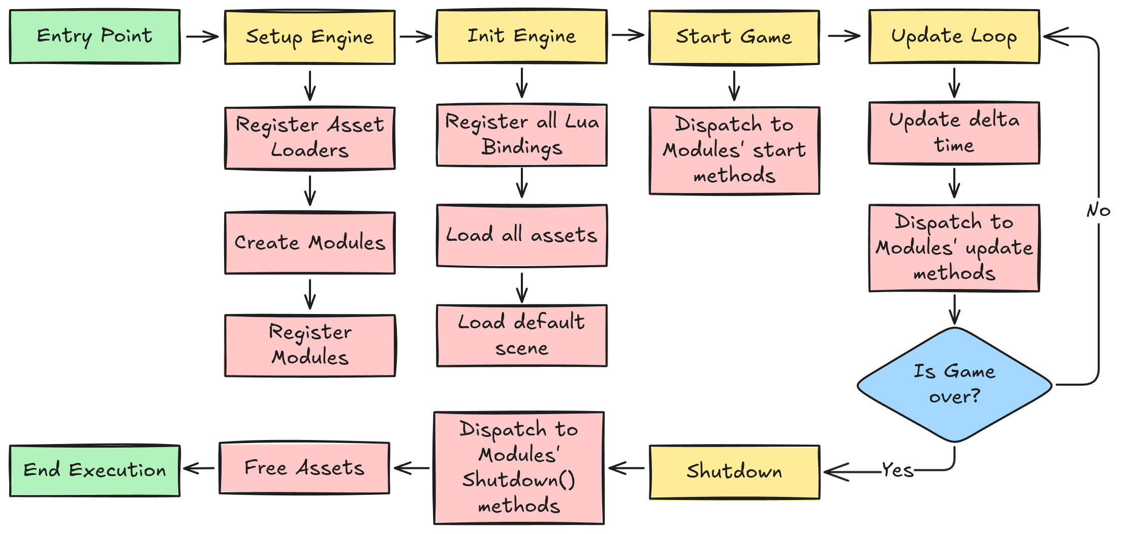
*Complete engine initialization and runtime flow from entry point through shutdown*
### Core Technology Stack
- Graphics: OpenGL 4.6 deferred pipeline (G-buffer, 4096×4096 cascaded shadows with PCF, SSAO, bloom, HDR IBL)
- Physics: Jolt Physics for high-performance simulation
- Animation: Ozz-Animation for skeletal animation systems
- Particles: Effekseer integration for advanced VFX
- Audio: OpenAL for 3D spatial audio
- Scripting: Lua with Sol3 binding framework
- Asset Loading: Assimp for 3D model import
- UI Framework: Dear ImGui for editor interface
- Serialization: Cereal library for scene persistence
- Profiling: Tracy
### Module Dependencies Graph
## Physics Integration
### Jolt Physics Implementation
**What this recording shows:** Jolt Physics running inside cpp-engine. Rigid bodies with mass and collision actually fall, stack, and interact in the engine's scene, not in a vendor sample. The recording is the author's runtime stepping a 6DOF simulation with the engine's RigidBody components.
CPP-Engine integrates Jolt Physics for multithreaded and stable simulation. The RigidBodyComponent and PlayerControllerComponent provide physics functionality accessible through the Lua scripting interface.
**Physics Features:**
- Rigid Body Dynamics: Full 6DOF simulation with proper mass properties
- Collision Detection: Efficient broad and narrow phase algorithms
- Character Controller: Smooth player movement with ground detection
- Trigger Volumes: Event-based collision detection for gameplay systems
## Animation System
### Ozz-Animation Integration
**What this recording shows:** Ozz-Animation skeletal playback on a skinned character inside cpp-engine. A full bone hierarchy is driving mesh skinning in the engine's renderer. The clip is the animation system the author integrated, sampling poses and rendering the skinned result in real time.
**Animation Features:**
- Skeletal Animation: Full bone hierarchy
- Animation Blending: Smooth transitions between animation states
- Pose Interpolation: Frame-accurate animation sampling
- Skinned Mesh Rendering: vertex skinning
## Particle Effects
### Effekseer Integration
**What this recording shows:** Effekseer particle effects running in cpp-engine's renderer: GPU particles with depth and 3D placement, used as an engine feature (fire, bursts, spatial FX) rather than a standalone VFX tool.
**Particle Features:**
- GPU-Accelerated Rendering: High-performance particle simulation
- Advanced Effects: Fire, smoke, magic, explosions, weather
- 3D Spatial Effects: Proper depth sorting and 3D effects
## **Editor Systems**
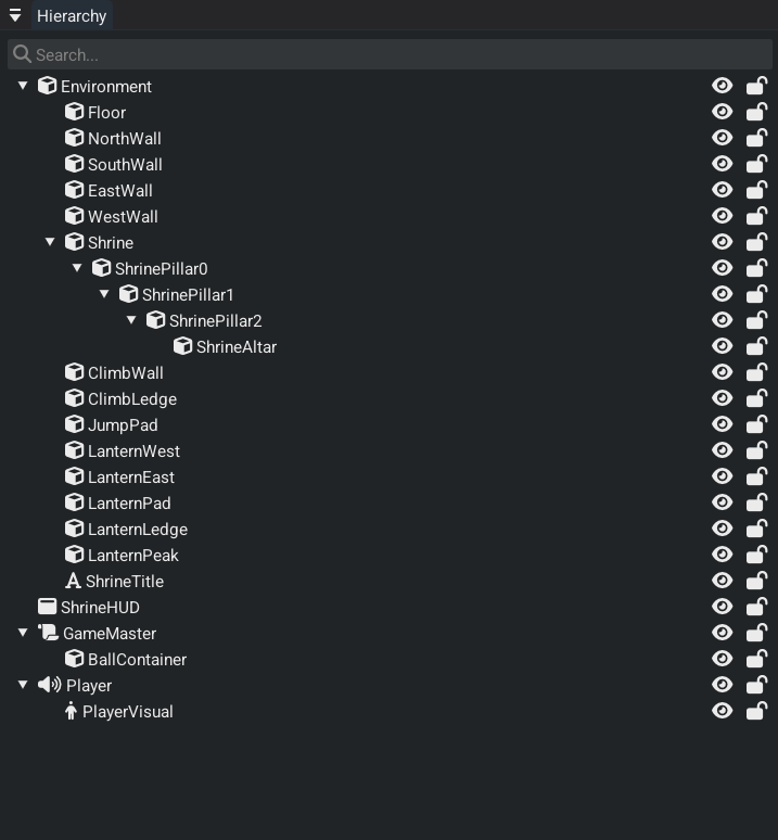
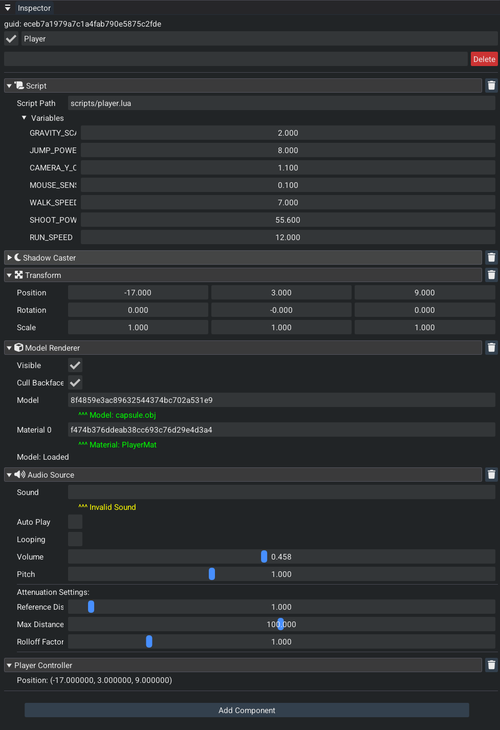
The editor is Dear ImGui in the same process as the runtime. Play/stop runs the simulation in place. Entities keep a persistent GUID. Hierarchy entities and assets drag onto inspector handle fields. Each component draws its own inspector UI.
Hierarchy Panel
- Parent/child transform hierarchy
- Right-click context menu for quick entity creation
- Drag-and-drop integration directly to EntityHandle fields in inspector
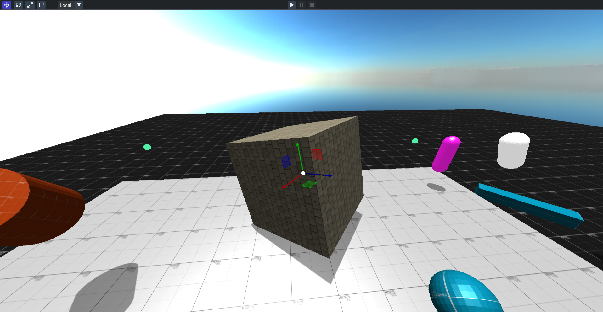
Scene View
- Interactive 3D viewport with real-time rendering
- Transform gizmos for translate, rotate, scale operations
- Mouse picking for direct entity selection
- Play/pause/stop controls for instant playtesting
Inspector System
- Entity management with delete, rename, and tag fields
- GUID display showing the persistent entity identifier
- Component headers with collapsible sections and individual delete buttons
- Custom component rendering where each component handles its own inspector UI
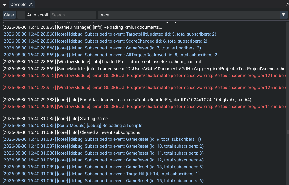
Console Window
- Filtered logging with search capabilities
- Auto-scroll support for development workflow
- Error tracking and debugging information
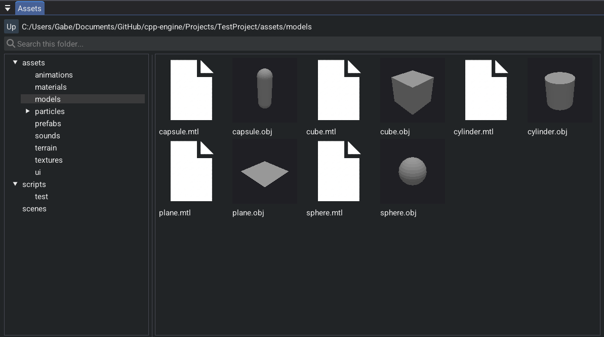
Asset Manager
- Tabbed interface for each asset type (Texture, Model, TerrainTile, SoundBuffer, Scene, Particle, Material, Animation)
- Asset preview and thumbnail support
- Drag-and-drop integration to AssetHandle<T> fields in inspector
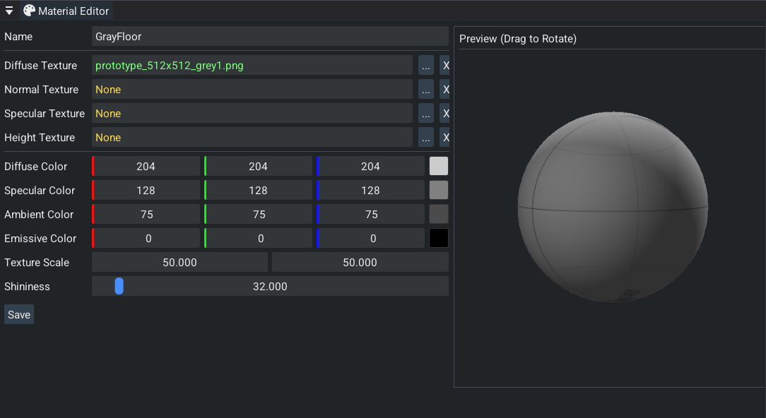
Material Editor
- Texture slot management for albedo, normal, and roughness maps
- Color and numeric property editing with real-time preview
- Material asset creation and saving
This project contains 20K+ non-blank lines of original C++ code for the engine, editor, and Lua bindings. That excludes Jolt, Ozz, Effekseer, and the rest of the vendor tree. Code is released under Apache License 2.0 and is available at [cpp-engine](https://github.com/gw12343/cpp-engine).
---
*Built with: C++17, OpenGL 4.6, Jolt Physics, Ozz-Animation, Effekseer, Sol3, Dear ImGui, Cereal, Assimp, OpenAL, Tracy Profiler*
[^1]: Amazon Lumberyard, *Amazon Lumberyard Bistro*, Open Research Content Archive (ORCA), July 2017. [developer.nvidia.com/orca/amazon-lumberyard-bistro](https://developer.nvidia.com/orca/amazon-lumberyard-bistro)
---
# Autonomous ROS2 robot
Canonical SPA: https://gabrielwest.dev/#/robot
Crawlable HTML: https://gabrielwest.dev/robot.html
# Autonomous ROS2 Robot
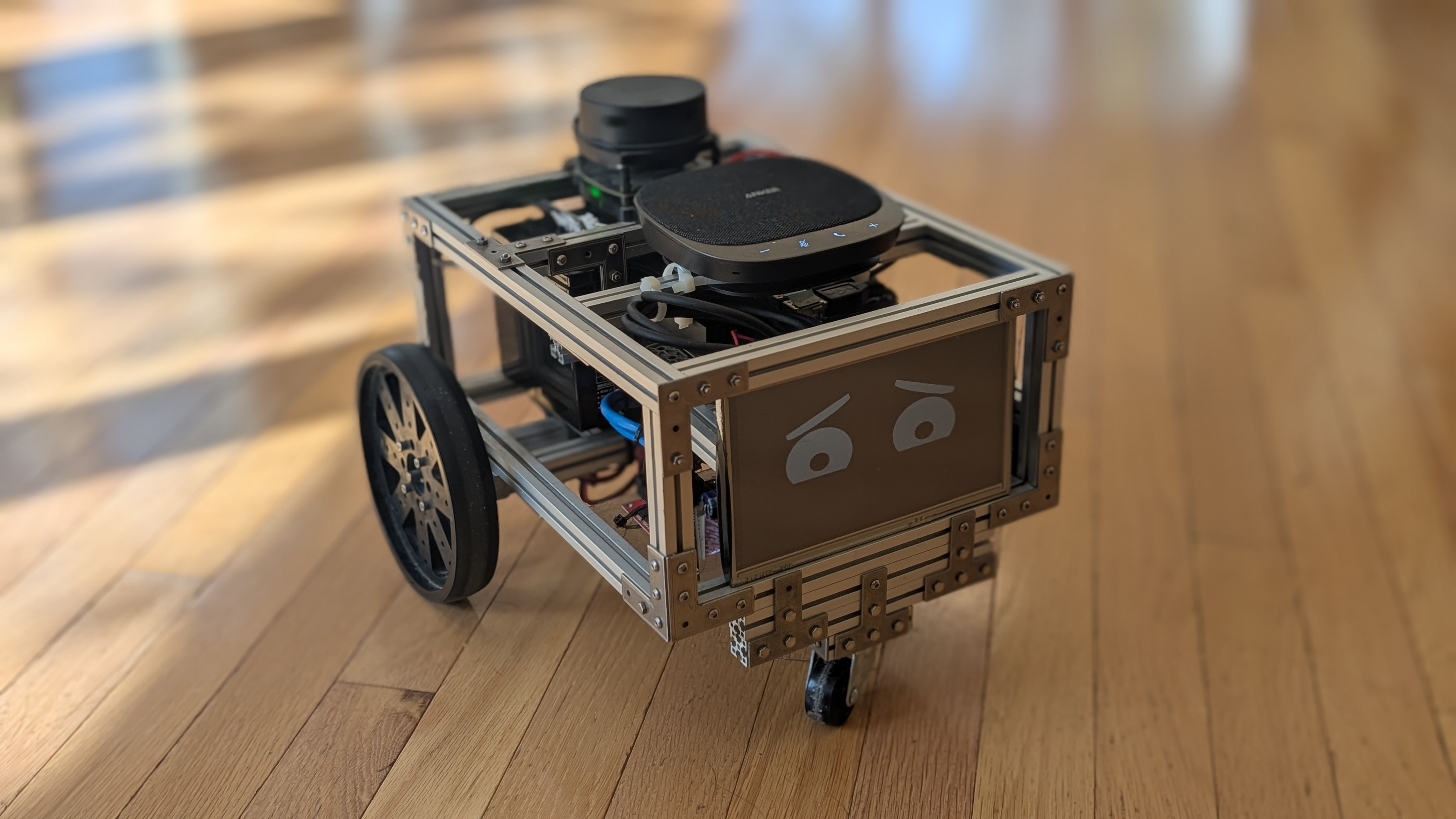
An autonomous differential-drive ROS2 Humble robot that incorporates LiDAR SLAM, encoder odometry, and Nav2 planning with a conversational voice stack (Riva STT → Llama 3 LLM→ Riva TTS) and an expressive on-screen face. The robot holds spoken conversations, with the LLM replying to your statements and questions. However, if it infers you wish it to perform a known action (navigation, emotion change), it issues a matching system command instead of a spoken reply. Everyday wording is enough, you do not have to use keywords or name the skill.
## System Demonstrations
### Navigation and Command Demo
**What this recording shows:** End-to-end voice-to-motion on the physical robot. Spoken "go do the dishes" is understood and refused ("I can't do that yet"), which is the model reasoning about capability, not a keyword miss. Spoken "can you go to the kitchen" is accepted ("on my way"). Nav2 produces a path on the dashboard and the robot drives into the actual kitchen, avoiding obstacles. NVIDIA Riva handles speech; Llama 3 maps language to a navigation goal; ROS2 Humble executes it.
Spoken “go do the dishes” is understood, then refused: the robot has no action for chores. “Go to the kitchen” matches a known navigation skill. Kitchen is a stored pose on a map built earlier. Nav2’s global planner produces a path to those coordinates, and the local planner follows it while steering around obstacles. Riva transcribes the speech, Llama 3 chooses the reply, and a ROS node starts that navigation when the reply is a command.
### Emotion Demo
**What this recording shows:** Llama 3 driving the robot's face and motion from unconstrained speech, not a canned keyword map. The eyes start sad. "Cheer up" is interpreted and the face switches to happy. A longer natural-language pep talk ("I'm going to ask you to do something and I need you to try your hardest") is parsed into a determined expression. "Navigate to the kitchen" is recognized as a nav goal; the robot moves while keeping that expression. Riva transcribes, Llama 3 selects an action from the robot's skill list (face state and navigation), and ROS2 plus the eye display carry it out.
The robot has an emotion system of different emotional states ['NEUTRAL', 'HAPPY', 'SAD', 'SURPRISED', 'INQUISITIVE', 'DETERMINED'], each associated with a distinct on-screen expression. The state is controlled through emotion-state commands issued by Llama 3. There is no keyword recognition, instead Llama 3 is prompted to issue emotion state change commands based on the flow of conversation. In this clip, Llama 3 decided when hearing “I want you to really try your hardest” to initiate a change to the “determined” emotional state.
### SLAM Demo
**What this recording shows:** Live SLAM on the robot. RPLiDAR scans feed an occupancy grid that grows as the platform is teleoperated through a real room. Odometry is fused with the laser. RViz shows the occupancy grid filling in during the run, which is the localization-and-mapping loop working on the Jetson, not a prerecorded map dropped onto the screen.
Real-time SLAM mapping demonstration in RViz showing map construction as the robot explores the environment. Controller input visible in bottom left shows manual teleoperation while the robot builds an accurate occupancy grid map using LIDAR data and odometry fusion.
## System Architecture
The project integrates five major subsystems:
- **Navigation Stack:** ROS2 Nav2 with LIDAR-based mapping and localization
- **AI Integration:** Llama3 LLM with voice input/output via NVIDIA Riva
- **Visual Interface:** Expressive eye display with emotional states
- **Motor Control:** Dual motor drive system with encoder feedback
- **Sensor Fusion:** LIDAR and encoder integration for precise positioning
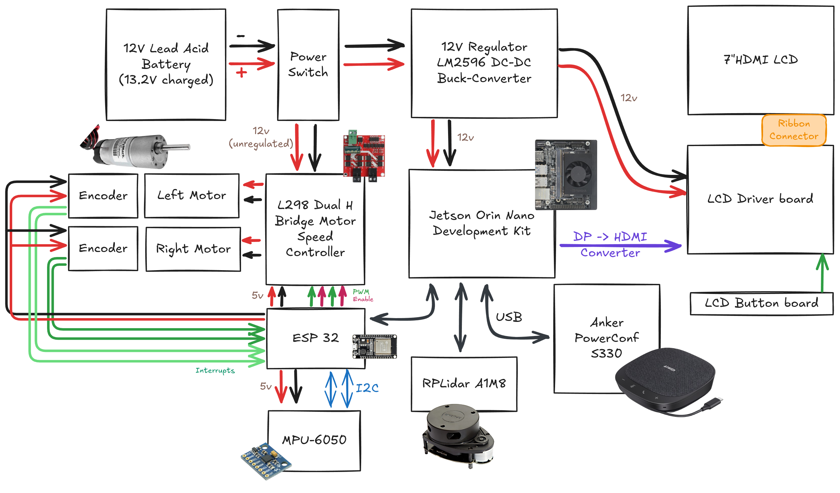
The Jetson Orin Nano runs ROS2 Humble. An RPLiDAR A1 on USB publishes LaserScan into Nav2’s costmaps. Wheel encoders on the ESP32 are converted to odometry so the robot knows how far it has driven. Mapping and going to a named place are separate steps. In the SLAM clip, the robot is teleoperated while LiDAR scans and odometry build an occupancy grid; that grid is saved as a map. Later, a name like kitchen is a stored pose on that already-built map. Nav2 loads the saved map, and the global planner produces a path to those coordinates, which is what happens in the kitchen clip.
Spoken audio is transcribed by NVIDIA Riva, the transcript is sent to Llama 3, and Llama 3’s reply goes to a text-to-speech node. Known-skill intent comes back as XML such as <COMMAND> navigate kitchen </COMMAND>. If the text received by the TTS node is parsed as a command, TTS initiates the command on the appropriate node (/global_planner, /eyes_node), otherwise text is directly synthesized to speech. Eyes are a browser page on the 7″ HDMI panel.
## Hardware Architecture
The complete electronics system can be seen here:
## **ROS2 Node Architecture**
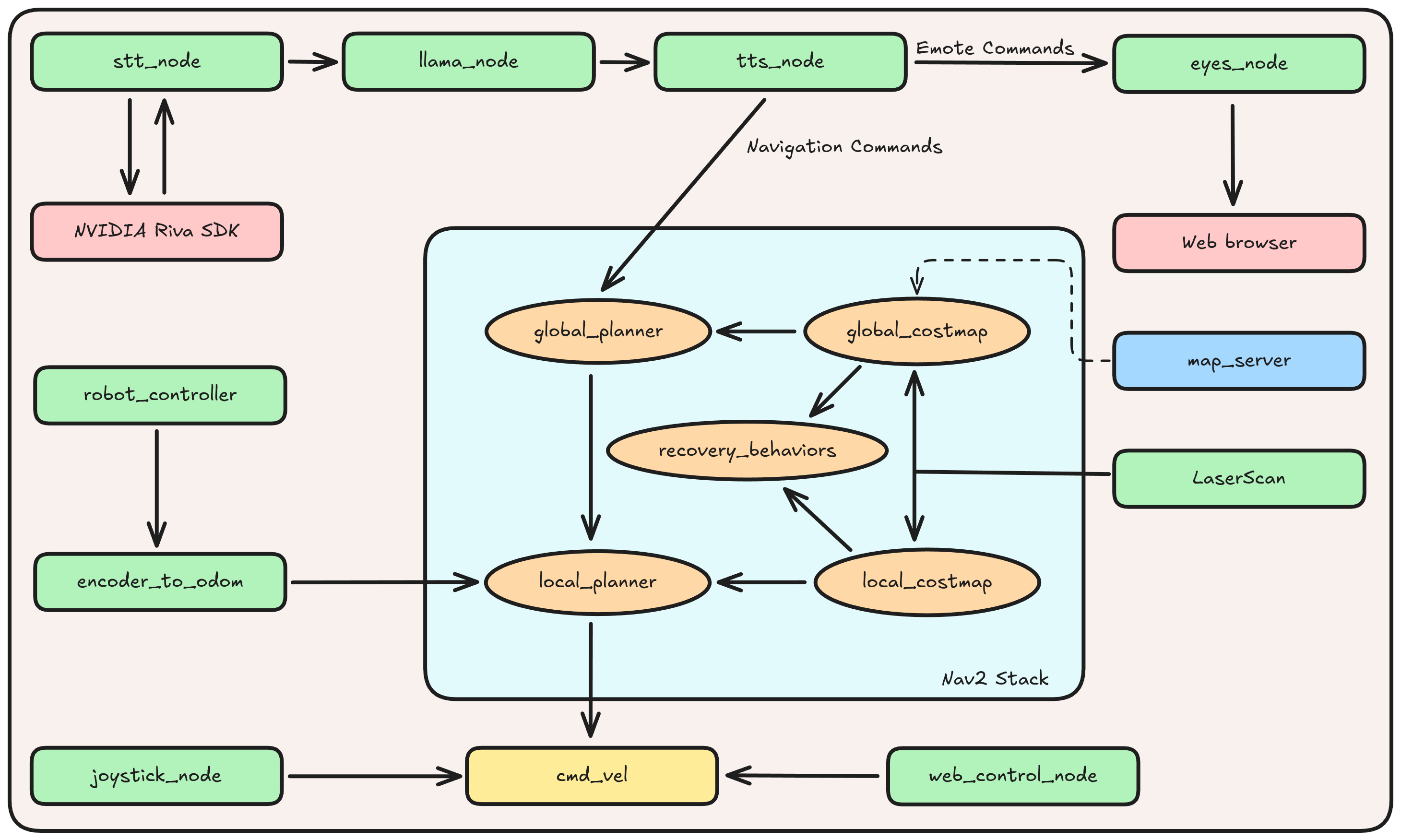
Topics:
```
/cmd_vel # Velocity commands to motors
/scan # LIDAR data
/odom # Odometry feedback
/voice_in # Speech-to-text output
/llama_out # LLAMA3 output
/tts_out # Text-to-speech input
/robot_state # Emotional state commands
/navigation_status # Current navigation state
```
The diagram is the map. Voice: STT node, Riva, Llama 3, TTS node, which forks to Nav2 and to the eyes. Nav2 takes LaserScan, a saved map, and encoder odometry. Recovery sits between the planners and the costmaps.
### Real-time Performance:
Motor control loops at 100Hz
Navigation updates at 20Hz
Voice processing with <750ms latency
---
*Built with: ROS2 Humble, NVIDIA Jetson Orin Nano, RPLiDAR, Llama3, NVIDIA Riva, ESP32*